What It Does
Two SX1280 radio nodes measure the straight-line distance between them via round-trip time-of-flight ranging. One node acts as the initiator — it sends ranging requests and computes the distance result. The other is the responder, which the SX1280's hardware ranging engine handles automatically with no firmware timing involvement. Both sites are fixed; one sits on a mountaintop for unobstructed line of sight to the other.
Calibration will be done at known distance and confirmed via a variety of local landmarks and externally measured points; methodology still to be determined. GPS co-ordinates will not be used in any way for distance, as the attempt is to obtain projection-agnostic distance based on physical principles rather than lights in the sky.
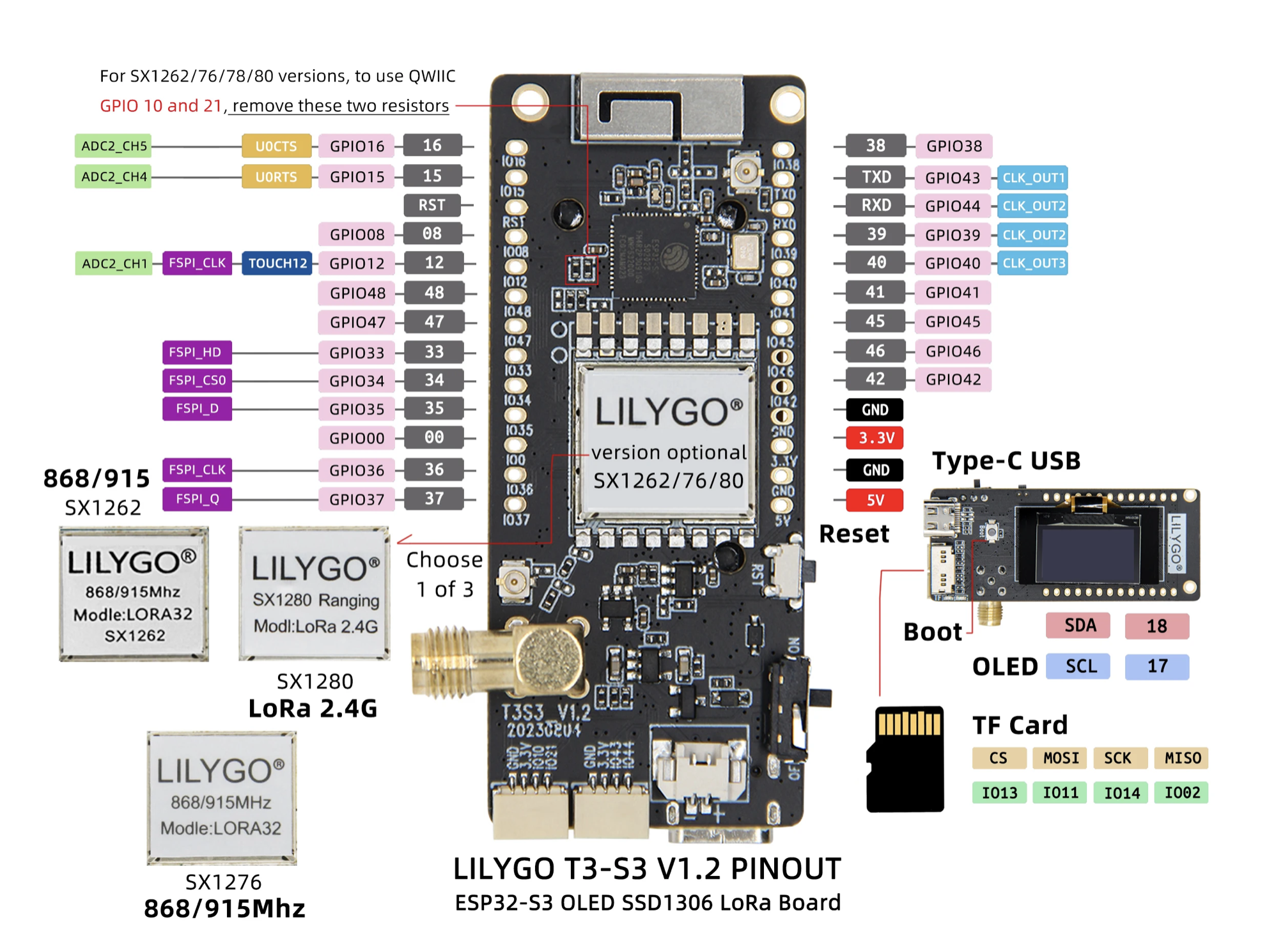
Hardware (per site — two identical builds)
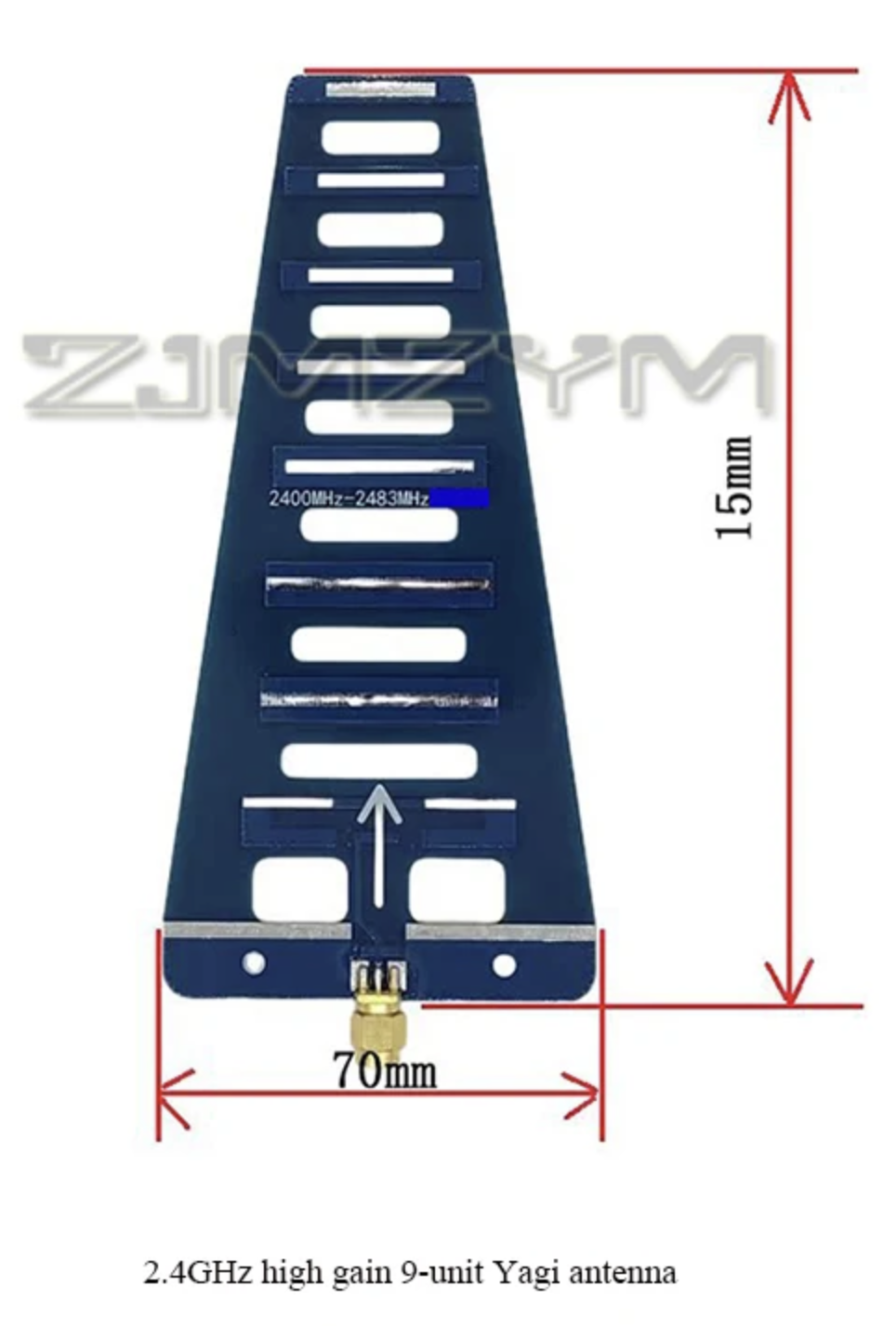
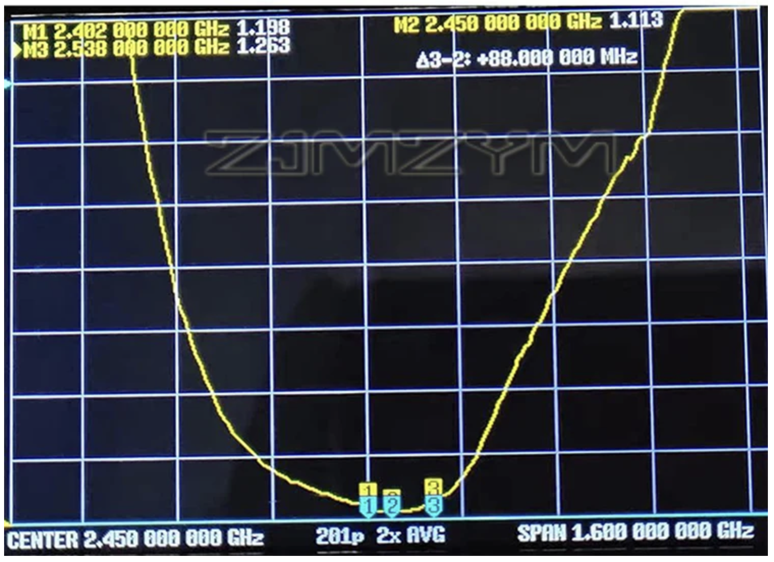
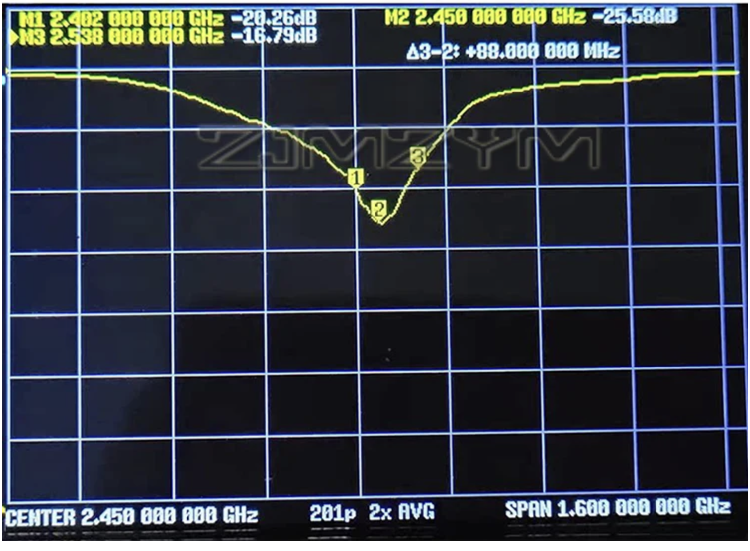
Antenna — VNA Measurements
Both traces centered at 2.450 GHz, 1.600 GHz span. The antenna is well-matched across the full 2.40–2.49 GHz ISM band.
Radio Configuration
| Parameter | Value |
|---|---|
| Chip | Semtech SX1280 (2.4 GHz LoRa ranging) |
| Frequency | 2450 MHz (2.4 GHz ISM band) |
| Bandwidth | 1625 kHz — widest available, best distance resolution |
| Spreading factor | SF9–SF10 (link margin is plentiful) |
| Output power | 13 dBm (SX1280 chip maximum) |
| Roles | One initiator, one responder — identical RF parameters required |
| Calibration | Known GPS site coordinates → computed great-circle distance as reference |
| Atmospheric model | GRIN tropospheric delay from BME280 P/T/RH readings |
Link Budget — 60 km
Power — 12 V Battery to 5 V (Field / Solar Site)
The T3-S3 runs from 5 V (USB / 5 V input) and regulates to 3.3 V on-board. At a solar or battery site the source is 12 VDC, requiring a DC-DC conversion stage.
| Approach | Notes |
|---|---|
| RECOM R-78E5.0-1.0 (recommended) | Drop-in sealed switching module, high efficiency, low noise, 1 A. One part, no tuning. |
| Quality buck (e.g. Pololu D24V10F5) | Pre-filtered, cleaner than bare MP1584 boards. Add output decoupling caps. |
| Buck → LDO two-stage | Buck does the efficient heavy lifting; LDO scrubs switching ripple. Cleanest rail. |
Whichever converter: add 100 µF electrolytic ∥ 0.1 µF ceramic at both input and output. The T3-S3's onboard LiPo charger provides a free UPS — a small LiPo trickle-charges from the regulated 5 V rail and carries the node through cloudy spells or brief battery dips.
3.3 V Direct — Bench / Low-Power Field Build
A regulated 3.3 V buck converter can feed the T3-S3's 3V3 header pin directly, bypassing the onboard LDO entirely. The same rail powers the BME280 sensor. A JST-2 connector on the buck output makes field connection clean and reversible.
| Connection | Detail |
|---|---|
| 3V3 buck (+) → T3-S3 3V3 header pin | Bypasses onboard LDO. Buck becomes the system regulator — must supply ≥ 500 mA peak. |
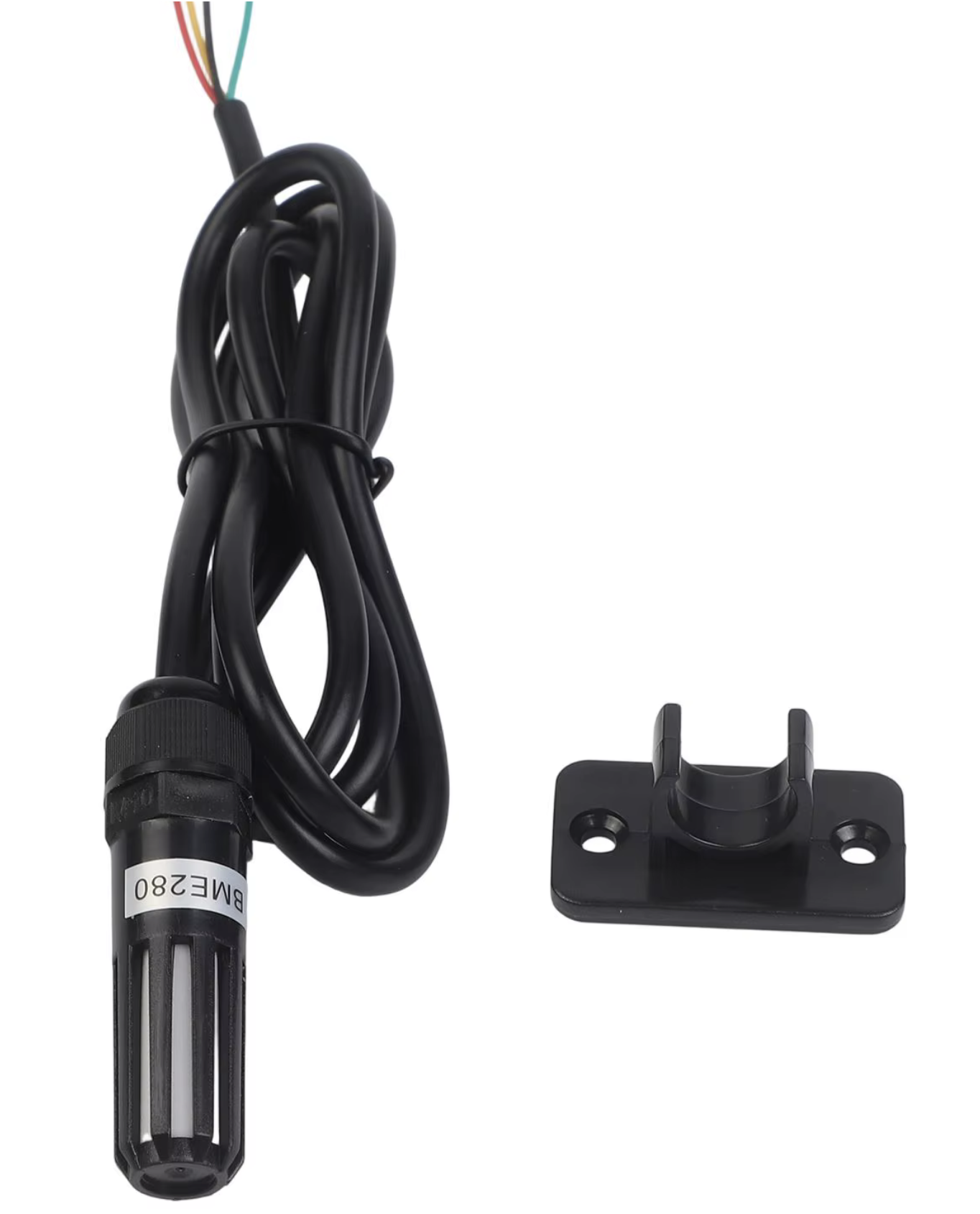
| 3V3 buck (+) → BME280 VCC & CSB | CSB tied high keeps BME280 in I²C mode. |
| GND → T3-S3 GND, BME280 GND & SDO | SDO to GND sets I²C address 0x76. |
BME280 Wiring
The BME280 shares the T3-S3's onboard I²C bus (hardwired to SDA = GPIO 18, SCL = GPIO 17). Both the OLED display and BME280 sit on the same two wires; I²C addressing keeps them separate (OLED 0x3C, BME280 0x76).
| BME280 pin | T3-S3 connection | Notes |
|---|---|---|
| VCC | 3V3 header pin (or 3V3 rail) | |
| GND | GND | |
| SDA | GPIO 18 | Shared with OLED |
| SCL | GPIO 17 | Shared with OLED |
| SDO | GND | Sets I²C address 0x76 |
| CSB | 3V3 | Holds device in I²C mode |
Installation Notes
| Topic | Detail |
|---|---|
| Polarization | Both Yagis must share the same element orientation (both vertical or both horizontal). A 90° mismatch costs ~20 dB. |
| Aiming | E-plane beamwidth is 48° — ±24° within 3 dB. Pre-aim by GPS great-circle bearing, correcting ~14–15° E magnetic declination in eastern BC. Fine-peak on live RSSI readout. |
| Fresnel clearance | Verify path profile clears terrain at the midpoint with room for the ~40 m first Fresnel zone plus ~50 m Earth bulge over 60 km. Run HeyWhatsThat or RadioMobile before deploying. |
| Enclosure | IP65 plastic (RF-transparent) box. Weatherproof the SMA joint. Add surge arrestor and ground strap if mounting on a metal mast at height. |
| Diagnostics | Low RSSI despite good aim → rotate one antenna 90° (polarization check). Still low → verify Fresnel / Earth bulge clearance before adjusting RF settings. |